Difference between revisions of "Weisshaupt's LCD Mechanism"
m (24 revisions) |
|||
| (10 intermediate revisions by one other user not shown) | |||
| Line 7: | Line 7: | ||
<br style="clear:both;"/> | <br style="clear:both;"/> | ||
[[Image:LCDMount.jpg|right]] | [[Image:LCDMount.jpg|right]] | ||
| − | In this method, the Monitor is Mounted to a custom made mount. The Mount consists of a 1/4 inch bolt, placed through the bearing of a 5 inch or larger plastic pulley (Like McMaster-Carr Part number 6284K61), placed thorugh a spacer, and then placed through a Hole drilled ina 2x4 and secured with a standard wingnut. Washers may be required to hold the Spacer firmly against the Pulley and the 2x4, and between the 2x4 and the wingnut. | + | In this method, the Monitor is Mounted to a custom made mount. The Mount consists of a 1/4 inch bolt, placed through the bearing of a 5 inch or larger plastic pulley (Like [[McMaster-Carr]] Part number 6284K61), placed thorugh a spacer, and then placed through a Hole drilled ina 2x4 and secured with a standard wingnut. Washers may be required to hold the Spacer firmly against the Pulley and the 2x4, and between the 2x4 and the wingnut. |
The Monitor is attached using bolts placed through holes drilled in the pulley using the Standard Vesa mount found on the back of almost all LCD displays. Sandwiched between the Pulley is a Pizza Pie Plate from Target. A pizza Pie PLate with holes is beneficial because the center of the plat can be more easily determined. The Very center of the plat needs a 3/4 inch hole which prevents the PLate from Binding on the mounting bolt. In addtion, 4 hols must be drilled in the plate that correspond to the VESA mounting holes on the Monitor. VERY OFTEN THESE HOLES WILL NOT BE ON CENTER, but vertically offset from a 4:3 aspect. If this offset is not taken into account, the Monitor will be to the left or right of center when rotated to its 3X4 aspect. Vesa Mounts use M4 .7 Metric Screws. You must choose a length that will fit thorugh the pulley, the pizza pie plate and fit snugly into the VESA mount without bottoming out. | The Monitor is attached using bolts placed through holes drilled in the pulley using the Standard Vesa mount found on the back of almost all LCD displays. Sandwiched between the Pulley is a Pizza Pie Plate from Target. A pizza Pie PLate with holes is beneficial because the center of the plat can be more easily determined. The Very center of the plat needs a 3/4 inch hole which prevents the PLate from Binding on the mounting bolt. In addtion, 4 hols must be drilled in the plate that correspond to the VESA mounting holes on the Monitor. VERY OFTEN THESE HOLES WILL NOT BE ON CENTER, but vertically offset from a 4:3 aspect. If this offset is not taken into account, the Monitor will be to the left or right of center when rotated to its 3X4 aspect. Vesa Mounts use M4 .7 Metric Screws. You must choose a length that will fit thorugh the pulley, the pizza pie plate and fit snugly into the VESA mount without bottoming out. | ||
| − | |||
[[Image:CabinetMount.jpg|right]] | [[Image:CabinetMount.jpg|right]] | ||
| Line 19: | Line 18: | ||
| − | Two more short extensions are mounted on top of the 2x4. The ends of these extensions are coated with Loop-side velcro, and hold the reed switches that acts as limit switches. (It is recommended that DigiKey part numbers CH404-ND and CH411-ND be used for the limit switches.) 2 More strips of loop-side velcro are attached to the Pizza Pie plate at the approximate locations where the Monitor will reach its 3x4 and 4x3 aspects. The Magnets that activate the Reed switches are mounted to these patches. | + | Two more short extensions are mounted on top of the 2x4. The ends of these extensions are coated with Loop-side velcro, and hold the reed switches that acts as limit switches. (It is recommended that [[DigiKey]] part numbers CH404-ND and CH411-ND be used for the limit switches.) 2 More strips of loop-side velcro are attached to the Pizza Pie plate at the approximate locations where the Monitor will reach its 3x4 and 4x3 aspects. The Magnets that activate the Reed switches are mounted to these patches. |
| − | If the monitor is extremely bottom heavy, or falls to one side or the other, A counterwieght should be mounted in the top-most corner of the list, or on the top-most corner which will first begin a downward rotation when moving to the new aspect. | + | If the monitor is extremely bottom heavy, or falls to one side or the other, A counterwieght should be mounted in the top-most corner of the list, or on the top-most corner which will first begin a downward rotation when moving to the new aspect. |
| − | |||
| − | |||
| − | + | Alternatively a simple lazy susan may be substituted for the pulley/bolt/pizza pie arrangement. | |
| + | == Electronics == | ||
| + | A small, high torque hobby motor with a high-traction wheel should be used. The GM2 or GM3 motor from [[Solarbotics]] upgraded to the higher torque Regular Motor 2 and a High traction, "extra grip" wheel is a good choice. The Motor should be driven by an "H-Bridge" circuit capable of providing adequate current and voltage for the motor. This circuit should also use Diodes to protect the logic and power circuits from the Motor's EMF noise as it starts and stops. The "Secret Motor Driver" board from Solarbotics incorporates this circuit into a VERY easy to assemble kit that will drive motors up to a 600ma current using the PC's +5V power supply. The circuit can be adapted to using a higher Voltage by adding a 5V regulator according to the instructions provided by Solarbotics. A Chip socket can also be used to make solding the kit together easier, and chip replacement a snap. The Circuit diagram below shows the correct connection of the Solarbotics Secret Motor Driver. If using another H-Bridge design, the Green and Orange Wires should be tied to the "CW" and "CCW" inputs of the H-Bridge. If you find you motor is turing the wrong direction, simply reverse the M1 and M2 wires to the motor. The Original Secret.exe program uses a truth table where pin2 = 1 and Pin 3 = 0 will rotate the MONITOR (not the motor) in the CW direction, and uses Low logic detection on pins 10 and 11. The newer edition of the program comes in the form of the DOSRotate and MALAROTATE plugin. This program is fully configurable and allow any of the truth tables documented here to be used (and also supports degaussing and switching of pins) By default it follows the KOZ319 convention of pins 2,3 used for H-Driver input, Pin 4 used for PWM strobing, Pin 5 used for Degauss and Pin 6 used for monitor off/on.(Links to these programs coming soon!) | ||
| − | Connection to the Parallel Port can be made | + | Connection to the Parallel Port can be made eiter by splicing an exisiting cable open, or by using a DB25 to RJ45 adapter. The +5V power and GND used are connected directly to the PC power supply. '''DO NOT ATTEMPT to use the +5v power on the parallel port: you WILL DAMAGE your motherboard!''' The 330 Ohm resistors on the sensor switches are also required to prevent potential damage from sinking too much current into the Parallel port when connected to +5v. |
[[Image:SecretSchematic.jpg]] | [[Image:SecretSchematic.jpg]] | ||
| − | + | [[Image:SecretSchematic1.jpg]] | |
| − | <br> | + | [[Image:SecretSchematic2.jpg]] |
| + | </br> | ||
== Program Control == | == Program Control == | ||
| Line 55: | Line 55: | ||
== Front End Integration == | == Front End Integration == | ||
| − | The secret.exe program can be called using a Batch File which also Calls MAME or it can be called under front end control. It was specifically designed for use with the | + | The secret.exe program can be called using a Batch File which also Calls MAME or it can be called under front end control. It was specifically designed for use with the [[Emulaxian/3D Arcade]] frontend, which allows a program to be called before or with the Mame executable, but should be adapbable for use with other front ends. |
The Specific 3DArcade configuration is: | The Specific 3DArcade configuration is: | ||
| Line 71: | Line 71: | ||
* [[Rotating Monitor]] | * [[Rotating Monitor]] | ||
* [[Arcade Cabinet]] | * [[Arcade Cabinet]] | ||
| + | |||
| + | == External Links == | ||
| + | |||
| + | Weisshaupt can be reached at jjo0@columbia.edu iwth any questions concerning this design | ||
Latest revision as of 09:58, 5 December 2013
This mechanism allows automatic programmatic Parallel port control of the rotation of a 4:3 LCD monitor up to 20in diagonal. It is designed to be a low cost (around $50) solution using readily available parts, with a minimum of programmatic and electronics experience required.
Mounting
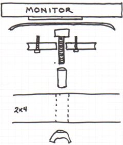
In this method, the Monitor is Mounted to a custom made mount. The Mount consists of a 1/4 inch bolt, placed through the bearing of a 5 inch or larger plastic pulley (Like McMaster-Carr Part number 6284K61), placed thorugh a spacer, and then placed through a Hole drilled ina 2x4 and secured with a standard wingnut. Washers may be required to hold the Spacer firmly against the Pulley and the 2x4, and between the 2x4 and the wingnut.
The Monitor is attached using bolts placed through holes drilled in the pulley using the Standard Vesa mount found on the back of almost all LCD displays. Sandwiched between the Pulley is a Pizza Pie Plate from Target. A pizza Pie PLate with holes is beneficial because the center of the plat can be more easily determined. The Very center of the plat needs a 3/4 inch hole which prevents the PLate from Binding on the mounting bolt. In addtion, 4 hols must be drilled in the plate that correspond to the VESA mounting holes on the Monitor. VERY OFTEN THESE HOLES WILL NOT BE ON CENTER, but vertically offset from a 4:3 aspect. If this offset is not taken into account, the Monitor will be to the left or right of center when rotated to its 3X4 aspect. Vesa Mounts use M4 .7 Metric Screws. You must choose a length that will fit thorugh the pulley, the pizza pie plate and fit snugly into the VESA mount without bottoming out.
The Pizza Plate should be painted with Spray-can Plasti-dip (available at most hardware stores) This increases the friction between the plate and the driver wheel
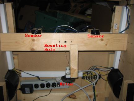
A wood extension is attached underneath the central 2x4 and the motor is mounted to it in such a way that the Motor's drive wheel makes solid contact with the Pizza Pie Plate. The extension MUST be mounted on the bottom of the 2x4 because any "play" in the mount will make it Fall into the motor wheel, rather than away from it.
Two more short extensions are mounted on top of the 2x4. The ends of these extensions are coated with Loop-side velcro, and hold the reed switches that acts as limit switches. (It is recommended that DigiKey part numbers CH404-ND and CH411-ND be used for the limit switches.) 2 More strips of loop-side velcro are attached to the Pizza Pie plate at the approximate locations where the Monitor will reach its 3x4 and 4x3 aspects. The Magnets that activate the Reed switches are mounted to these patches.
If the monitor is extremely bottom heavy, or falls to one side or the other, A counterwieght should be mounted in the top-most corner of the list, or on the top-most corner which will first begin a downward rotation when moving to the new aspect.
Alternatively a simple lazy susan may be substituted for the pulley/bolt/pizza pie arrangement.
Electronics
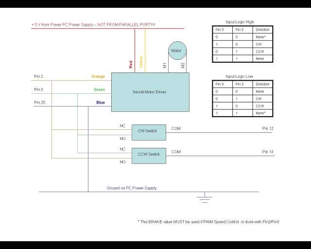
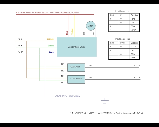
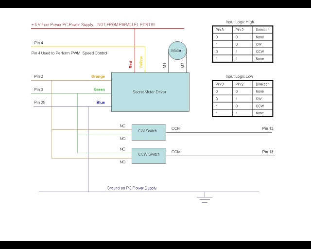
A small, high torque hobby motor with a high-traction wheel should be used. The GM2 or GM3 motor from Solarbotics upgraded to the higher torque Regular Motor 2 and a High traction, "extra grip" wheel is a good choice. The Motor should be driven by an "H-Bridge" circuit capable of providing adequate current and voltage for the motor. This circuit should also use Diodes to protect the logic and power circuits from the Motor's EMF noise as it starts and stops. The "Secret Motor Driver" board from Solarbotics incorporates this circuit into a VERY easy to assemble kit that will drive motors up to a 600ma current using the PC's +5V power supply. The circuit can be adapted to using a higher Voltage by adding a 5V regulator according to the instructions provided by Solarbotics. A Chip socket can also be used to make solding the kit together easier, and chip replacement a snap. The Circuit diagram below shows the correct connection of the Solarbotics Secret Motor Driver. If using another H-Bridge design, the Green and Orange Wires should be tied to the "CW" and "CCW" inputs of the H-Bridge. If you find you motor is turing the wrong direction, simply reverse the M1 and M2 wires to the motor. The Original Secret.exe program uses a truth table where pin2 = 1 and Pin 3 = 0 will rotate the MONITOR (not the motor) in the CW direction, and uses Low logic detection on pins 10 and 11. The newer edition of the program comes in the form of the DOSRotate and MALAROTATE plugin. This program is fully configurable and allow any of the truth tables documented here to be used (and also supports degaussing and switching of pins) By default it follows the KOZ319 convention of pins 2,3 used for H-Driver input, Pin 4 used for PWM strobing, Pin 5 used for Degauss and Pin 6 used for monitor off/on.(Links to these programs coming soon!)
Connection to the Parallel Port can be made eiter by splicing an exisiting cable open, or by using a DB25 to RJ45 adapter. The +5V power and GND used are connected directly to the PC power supply. DO NOT ATTEMPT to use the +5v power on the parallel port: you WILL DAMAGE your motherboard! The 330 Ohm resistors on the sensor switches are also required to prevent potential damage from sinking too much current into the Parallel port when connected to +5v.
Program Control
The Parallel Port wires are set and Monitored using a Program written in Visual C++ for use with Windows XP. Because Windows XP does not allow direct access to the communications ports, this program also requires a Parallel port driver. You can Download both the Driver and the program using the following links
Parallel Port Driver: inpout32.dll
The inpout32.dll should be placed into the Windows/system32 folder
Because the Mount is freely rotating on a bearing, Momentum and Speed must be controlled to obtain accurate placement. The Secret.exe program has 5 required paramters: Direction (a string that is either “3x4” or “4x3”) , 3x4 on-time, 3x4-off-time, 4x3 on-time, 4x3-off-time. (Note: if the monitor is rotating in the wrong direction, simply reverse the leads going to the motor – If it doesn’t stop in the right place, check that you are using the correct sensor)
The secret.exe program sets pin2 or pin 3 depending on the direction desired, and then switches everything off (brake mode) when it senses the correct limit switch has been hit. It does this by monitoring pins 10 and 11 (the status pins) to see when they go “high”. Pin 25 is connected to the signal ground.
Varying on-time and off time will determine how long the motor will be on or off based on a simple FOR loop. The For loop checks to see if the limit switch has been hit but otherwise just counts to the number specified in on-time/off-time. This allows the motor to be pulsed at any rate and duty cycle, and in either direction. Experiments have shown that numbers around 5000 work best with the Solarbotics motor, though other values may work better for other motors and designs. The values should be set so that the motor is just crawling when it reaches the limit switch. Once the limit switch is reached, the program STOPS rotation, and applies the motor "brake"
Front End Integration
The secret.exe program can be called using a Batch File which also Calls MAME or it can be called under front end control. It was specifically designed for use with the Emulaxian/3D Arcade frontend, which allows a program to be called before or with the Mame executable, but should be adapbable for use with other front ends.
The Specific 3DArcade configuration is:
Edit the Emulator's cfg file (for mame this is femame.cfg), section 3 should have a line similar to :
runbefore|c:\secret.exe $17 5000 5000 5000 5000/hidden/false |#fullexe|Format: commandline/runmethod/wait.
And the front end should be configured for Rotation by editing the fe.cfg, section 4 thus:
skinsautorot|true|#boole|When set to true the fe will after running a game check if field 15 of a gamelist entry contains Horizontal or Vertical and show from the current skinset the first skin if Horizontal is found and the second skin if Vertical is found. Ideal for rotatable monitors.|
See Also
External Links
Weisshaupt can be reached at jjo0@columbia.edu iwth any questions concerning this design
