GORF joystick
Contents
About the Gorf joysticks
Gorf includes two different joystick styles.
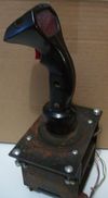
The Gorf Upright and Mini utilize a Control Grip joystick similar to other Midway games such as Satan's Hollow and TRON. The joystick is molded in black plastic with a semi-opaque black and red grid patterned lens panel on the back. While the Control Grip is considered an 8-way, it is constructed with a small circuit board utilizing optical sensors instead of mechanical switches.
The Gorf Cocktail Control Assembly uses a ball style joystick with leaf switches (as opposed to the optical board on the Control Grip).
Gorf Control Grip Assembly
Description
The Control Grip has three immediately noticeable differences from other similar Control Grips.
- The molded grip is comprised of black plastic as opposed to translucent blue (TRON) or translucent red (Satan's Hollow).
- The shaft is straight as opposed to a forward leaning shaft eg Discs of TRON.
- Uses a circuit board with optical switches instead of mechanical switches.
The joystick has similar dimensions to the TRON joystick.
Repair & Replacement
Mechanically, the stick is the optical version of the Happ Controls "Heavy Duty 8-way Trigger Joystick". (Whether the appropriate replacement parts can be ordered from Happ and fitted to the Gorf Control is unconfirmed as of this writing.)
Some common reported damage to the grip assemly include a cracked face plate and cosmetic damage to the plastic grip from rings. The joystick also sports two .08 amp 14v wedge base lightbulbs behind the faceplate and these may need replacing as well. It is possible to locate wedge base LED bulbs as a direct replacement.
Circuit Board
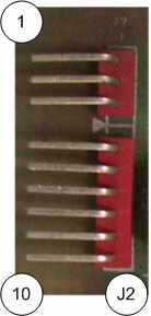
The circut board centers around a single LM339N IC, a Quad Voltage Comparator, and four SPX11879-11 optical transmitter/reciever packages. Also on board is a 5-pin .1 DP SIP molex connector (pin 2 is either missing or unconnected) and a 10 pin .156 SIP molex connector (with pin 4 missing or a 7-pin and a 3-pin molex connector with appropriate spacing.) A collection of resistors and capacitors complete the board. Not noted in the GORF service manual are two 0.1 mfd capacitors, labeled BP, near R3 and R10.
Identifying markings on the PCB:
MIDWAY MFG. CO. 1980 ©
ALL RIGHTS RESERVED
A080-91379-A000 MIDWAY MFG A BALLY CO.
A082-91379-A000 CONTROL GRIP ASSY.
The Gorf operators manual states the correct model number for the circuit board is A082-91379-A000.
|
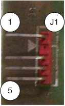
J1 pin assignment from pin 1 to 5 (top to bottom in photo to the right) is:
|

|
Gorf Control Assembly
Coming soon.

