Build an OND designed cab Metropolis
This is an example project to illustrate how to build your own arcade cabinet. Forum user Ond has created a topic on the forum with a step-by-step guide. This wiki page compiles all steps into a single page. Part of the text on this page is straight from Ond's forum post. The project is ongoing, for updates please check the forum for the latest update. We will try to keep the wiki page as up to date as possible.
Contents
Goal
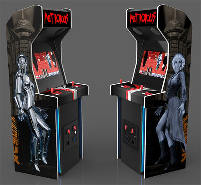
The goal of this project is to build a cabinet that looks like these digital concept renders:
Step 1: Design
Link to the forum message The design is sketched out first (the concept above renders are based on the digital plans). To design your own cabinet you can sketch and measure it using pen and paper or technical design software.
Plans
The plans for this build are available on the forum here: Imperial measurements or Metric measurements.
Step 2: Cutting the sheets of wood
Tools
I won't be going over the basics of using any of these tools, that's kind of assumed. If you're new to any of them, I recommend taking the time to learn about their use and practise on scrap timber before taking to your arcade project with them. Read the wiki page for more information on tools.
Wood
This project uses sheets of MDF. See wood products on this wiki for more information.
Cutting the wood
We need firstly to transfer the panel dimensions from the plan to a 4x8 sheet. The main thing here is to stay square, I don't mean be uncool, I mean that every line you draw with a pencil from the plan (other than curves or angles) needs to remain 'square' with the sheet. The best thing for this is a set square ruler, or T-square ruler, preferably a big one! I have a few in my garage, including some with an edge to position against a panel edge. The measurements can be transferred to MDF sheet by working from a reference corner. Other than a set square, a good tape measure, a long straight timber edge and a protractor are all I'd use for this. When we come to rounding off curves on the side panels these arcs can be marked with a pair of compasses (or just a compass for short).
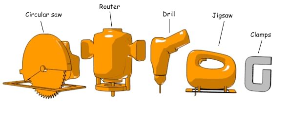
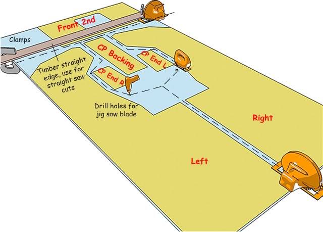
When the first 4x8 sheet is drawn up we can think about roughly cutting up the sheet into smaller more manageable panels. Even though I do have a saw table, I wouldn't try to cut up a sheet that size with it. Before I ever had a saw table I just had a cheap circular saw. I'd either use the fence on the saw (the guide attachment) of I'd use a straight piece of timber, clamped down to run the saw base along for a straight edge. In this instance we'll use both the jigsaw and circular saw to divide up the 4x8 sheet. The drill comes in handy to drill some holes at junctions in the cutting lines to put the jigsaw blade into.
The first panels we'll concentrate on are the side panels of the cab, everything kind of follows on from getting these prepared. We'll come back to the other smaller panels later on.
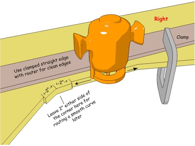
Obviously with a saw bench the next steps would be easier, but as I said, with some patience,some clamps and the straight edge you can make most of the cuts with just a hand held power saw. The shorter cuts near the Bezel area should just be cut as closely as possible to the pencil lines with the jigsaw. Leave about 3/4" outside of lines which intersect but which will later be routed to a smooth curve. The next few diagrams help to explain what I'm on about here.
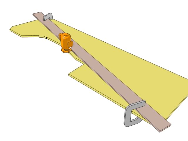
So we have a panel now which has been accurately cut along pencil lines where possible and rough cut near other lines where necessary. Time to prop the panel up on a bench or table and switch to the router! Many routers (but not all) have a base plate with one straight edge, in the same way we used the straight timber edge and clamps with a saw, we can also use a router to cut precise straight edges. First we're using just a standard straight bit in a 1/2" collet.
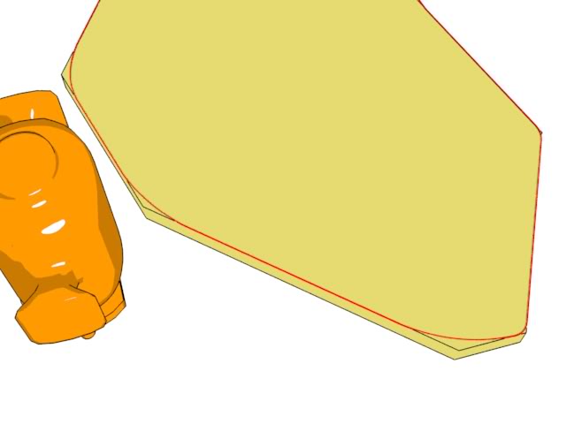
Important!-This cab design does have rounded off inner and outer corners. We need to leave something to refine into a curve later, mainly in this area here.
Once all the remaining edges are routed cleanly along the pencil guidelines we can focus on rounding off those corners. At this point there are a number of options. People confident with a router can just choose to free hand cut very near an (marked with a compass) arc pencil line and then sand this down to a final curve. This would be my approach. I get within a few mil *cough* err I mean fractions of an inch of the line and then take a small paint can wrapped in rough grade sandpaper and just hone an inner arc. Outside corners I'd route away most of the material sand and then refine with a mechanical sander, or hand sand with a sanding block. An alternative approach is to first make a thin (1/4") template of an arc and then use a flush trim bit to cut out the arc on the panel. Either way we want clean curves on these areas as well around the top of the cab. The T-molding is going to go nicely around these.
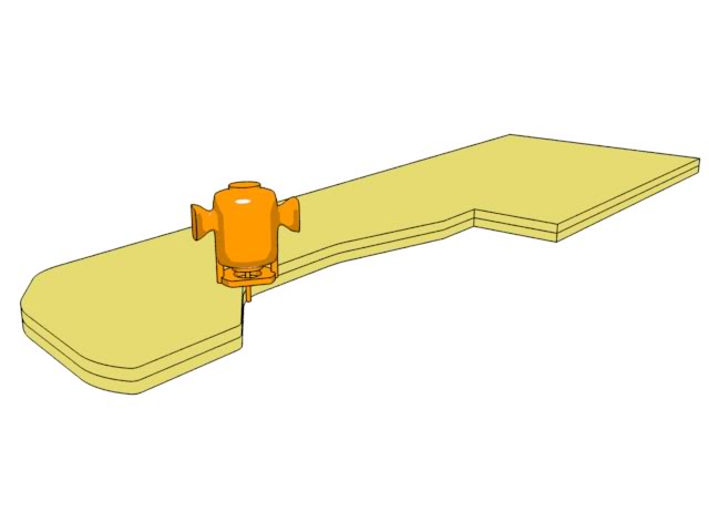
Side panels nearly done! We only need one accurately cut panel which we can clamp over the top of the other rough sawn panel and using a flush trim router bit make a duplicate panel from. TIP!-Trim the remaining panel as close as possible to the cutting line with a jigsaw first, this will make the routers work (and yours!) much easier.
I totally managed to leave the clamps out of that diagram, always remember to clamp the pieces together firmly for this type of work. TIP!-Use pieces of plywood between the surface of your panel and clamps to prevent denting the surface.
Step 3: Joining the panels
Having cut out the all the panels for this cab as per the cutting plan we can now get started on making the first few joins. Before we get into that, some thoughts on joinery methods. I’ve seen some discussion on the forum regarding gluing, using screws, other methods, screwing through panels from the outside etc. I use both glue (MDF specific or PVA white glue) and broad threaded countersunk screws designed for particle boards. I don’t usually build a cabinet with a view to pulling it apart again and try to put in some thought to access the inside where needed. Using screws and glue allows me to accurately position panels where they are just butt jointed and then the right glue for a permanent strong join.
I’ve seen some members using biscuit joinery for really clean looking results. I have used biscuit joinery myself for various cabinets (not just arcade ones) including 45 degree matched bevelled edges and the results can be really pleasing with the right equipment. Other techniques I’ve used include glued only cabinets using rebated panel ends and matching slots which I learned from my dad over the years, particularly with marine grade plywoods.
To make this design accessible to more people I’ve kept it very simple, just using bracing timber, butt joins, screws and glue. Is it OK to screw from the outside of a panel into an internal brace? What about the hole, and painting etc? With the right finishing this is not a problem at all.
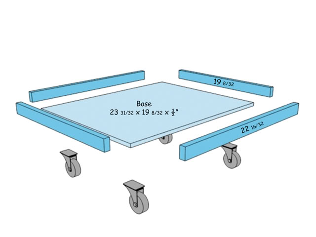
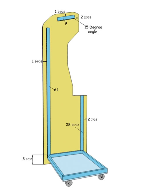
I’ve used a bit of colour system in the diagrams just to indicate where panels or timber are in addition to the panels from the cutting plan. These are coloured blue. All bracing timber is just standard 1 x 2” which I see is actually ¾” x 1 ½” (19mm x 38mm). 2 x 2 could also be used. This cab will be sitting on a base fitted with caster wheels, as many builders start by constructing this first, let’s start with that also.
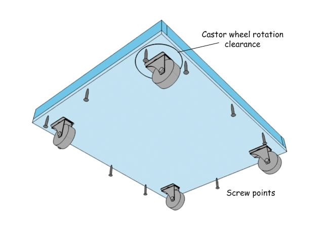
Choose caster wheels which are strong enough to handle the fully loaded cab, each wheel should be rated at least 50-60 kg. My preference is for casters with smaller wheels if you can find them. As the diagrams show the base is just constructed by pre-drilling the base panel and brace pieces and then gluing and screwing them together.
hen attaching the casters make sure you allow for the turning circle each needs, no part of the caster should protrude over the edge of the base unit as this will be positioned at a set height internal to the cab, all caster frames should have a clear turning circle to allow easy movement in any direction when needed.
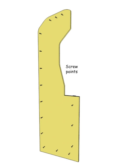
Next position the brace pieces as shown using the guide measurements. I’d trace with a pencil and then pre-drill the panels for screws points. Glue and screw the bracing pieces to each side panel as shown.
Attach one side to the base, butt joining the brace on the base tight up against the brace end on the panel. The height of the base allows for some clearance of wheels of around 1 ½” radius without having them on display. If you use caster wheels of a different radius you will need to adjust the height at which the base is attached to allow the wheels to clear the bottom of the cab.
Repeat with the other side panel.
