Wiring
Contents
Wiring Techniques
This page will cover the different types of wiring practices to better help you decide on the best way to wire up your project.
Selecting Wire
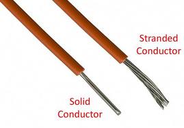
The size and type of wire used depends on the type of circuit it is being used in. Larger diameter wire is required for higher amperage circuits (A/C circuits of monitors and power supplies), whereas smaller diameter wire can be used in lower amperage circuits (control circuits). 22-24 gauge wire is a typical size used for wiring up control panels. 16-18 gauge wire is common for A/C power lines for things like power supplies and monitors. There are two basic types of wire: stranded and solid. Solid wire is more rigid and holds its shaped better than stranded wire. However, stranded wire is more flexible and easier to work with than solid wire.
Solid Wire
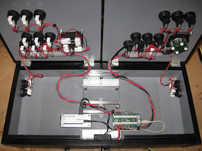
Typically, the only times you'll see solid wire being used in a project is when the builder uses CAT5 cable. Many people in this hobby come from computer backgrounds and use what they are familiar with, which is why some choose to use CAT5 cable for wiring their controls. They get multiple conductors in an easy to manage package. The wires inside the CAT5 cable are color coded which can make things a little easier when wiring up your controls. Here is a clean example, done by user TopJimmyCooks, of a CP wired using mainly CAT5 cable:
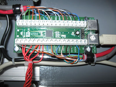
And a close up of his CAT5 wired to his interface of choice for this project, an I-PAC:
Stranded Wire
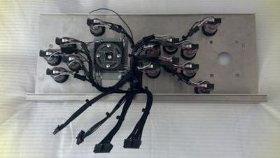
Wiring harnesses in original cabinets utilized stranded wire. Often called "hookup wire", it is readily available from auto parts stores and home improvement stores. Many builders choose to use stranded wire in their projects. Stranded wire is easier to crimp and solder than solid wire. Here is an example of an installed CP harness made with stranded wire:
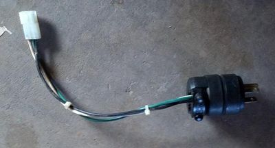
Here is a power plug wired to a Molex connector, using 16 gauge stranded wire, to connect to a stock arcade machine power supply harness:
Connecting Wires
There is a vast variety of different types of connectors to choose from for wiring your project. While they all will work, some are better/safer to use than others. Sure, you can simply twist two wire ends together and tape the connection, but that is not very safe. The easiest safe way to connect wires is by using some type of connector. You can also solder wires together to create a strong, dependable connection.
Common Connectors
The most common way of connecting one wire to another is by using one of the following types of connectors. These connectors can be found at any hardware, auto parts, or home improvement store. They can come in either insulated or non-insulated varieties, but it is always wise to insulated connectors to reduce the likelyhood of unintentional short circuits.
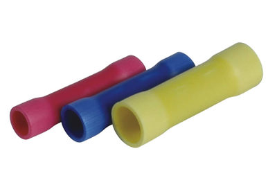
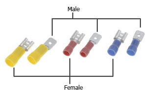
You will notice that many of these connectors come in red, blue, and yellow. This color code is used to indicate a range of wire gauges that the connectors should be used with. Red is for 18-22 gauge wire, blue is for 14-16 gauge wire, and yellow is for 10-12 gauge wire.
Wire Nuts
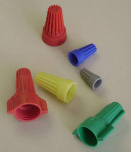
Wire nuts are most commonly used in electrical systems of buildings. You will see them used to connect the building's wiring inside electrical boxes for lights, switches, and outlets. They mostly used with solid wire, but can be used with stranded as well. They make for a quick, reversable wire connection. No crimping tool is needed, only wire strippers. Typically not recommended for use in this hobby.
Scotch Locks
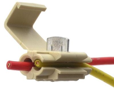
Scotch locks are the lazy man's connector of choice. No tools are required for the scotch lock. The scotch lock makes the connection between the wires by piercing the wires' insulation and wedging the conductors into the internal grooves of the scotch lock. Not recommended, they're ugly, and there's a better way.
Butt Splices
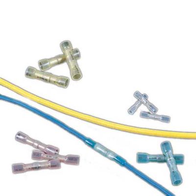
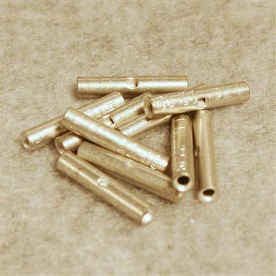
Butt splices connect one wire end to another wire end. The connection cannot be disconnected without cutting the butt splice out. They are handy for adding more length to a wire you find is too short. They are available in non-insulated, insulated, and heat shrink types. It is recommended that you used a heat shrink tube over a non-insulated butt splice.
Heat Shrink Butt Splices:
Insulated Butt Splices:
Non-Insulated Butt Splices:
Quick Disconnects
As their name implies, quick disconnects are designed to make a wire connection that can be disconnected and reconnected at will. Quick disconnects are used on nearly all arcade control panels. You will find them used on button and joystick microswitches. They commonly come in three different widths: .110", .187", and .250". The most common width used on arcade parts is .187". Many microswitches have a shouldered terminal which allows the use of either .187" or .250" quick disconnects. They are available in a male for female configuration. Since the microswitch terminals are male, female quick disconnects are used to connect wires to those terminals. There is a wide variety of quick disconnects as well.
Bullet Connectors
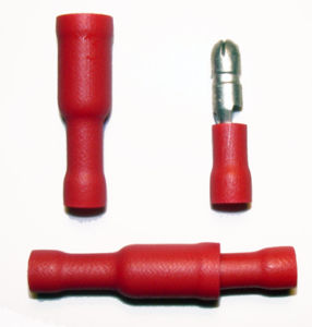
Bullet connectors are similar to quick disconnects in the fact that they can be disconnected and reconnected at will. However, this type of connection isn't typically found on electrical parts such as switches. These can be used in a similar manner as butt splices if you want to have a particular connection be able to be disconnected without cutting wires.
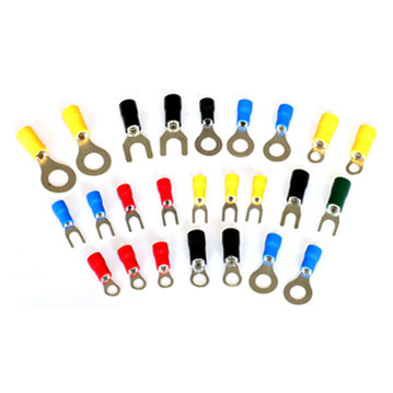
Ring/Spade Terminals
Ring and spade terminals are typically used to connect a wire to a screw terminal, such as found on arcade switching power supplies and many earth ground connections. To remove a ring terminal, the screw has to be completely backed out. However, to remove a spade terminal, the screw only needs to be loosened to allow the spade terminal to be slipped out.
Specialty Connectors
Along with the common types of connectors listed above, you will also encounter other types of "stock", "specialty", or "professional" connectors. The most common of these you'll find in original arcade machines are Molex type connectors. You will also find connectors made by other manufacturers, such as JST. These connectors are typically a hard plastic housing that contains multiple wires. A terminal pin is crimped onto the end of each wire, and the pins then lock into the housing. There are male and female pins, as well as male and female housings. Normally, male pins will install in female housings which mate with female pins installed into male housings.
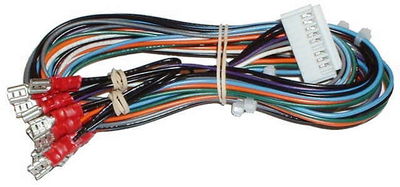
Vendors often offer products that incorporate screw type terminals for easy installation. However, some products are also available that utilize the use of some type of specialty connector, usually one that connects to a straight pin header on a PCB. Vendors will offer premade harnesses for use with these products, but that doesn't mean you can't make your own. With the right tools, you can make your own harnesses with these professional looking connectors. The tools will be covered in a following section.
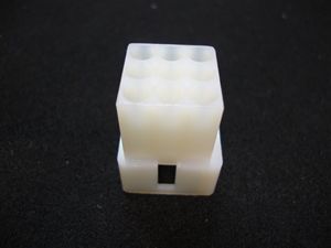
Connector Housings
Here is an example of the Molex connector type often found in arcade machines (this is a male housing):
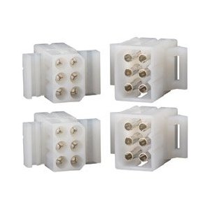
Male and female housings with pins installed:
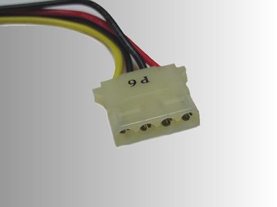
Here is another type of Molex connector often found in this hobby, a connector of a computer's power supply harness. This is a male housing and if you look closely you can see that the terminal pins are female:
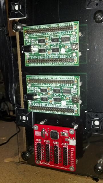
Here are some examples of interface boards that utilize straight pin headers. Two of Ultimarc's PACLED64s on the top and Paradise Arcade Shop's Lono2:
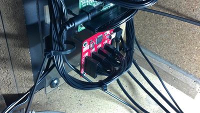
Here those same interface boards are wired up with homemade harnesses using connectors manufactured by Molex. The headers used on these interfaces are a common size and pitch (the same as what is used for USB headers on computer motherboards) and other manufaturers also make connectors to mate with these types of headers:
Here is a kick harness that uses a JST connector to connect to the game PCB:
Terminal Pins
Terminal pins are made specifically for use with their respective connector housings. Manufacturers and distributors usually make note of which pins are to be used with which housings. Most terminal pins require a special crimp, which can be made with a crimping tool designed to make that particular type of crimp. Once the pin has been crimped to the wire, it can be inserted and locked into the connector housing.
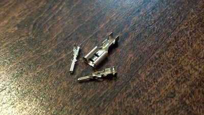
Here is an example of some terminal pins (and also a quick disconnect that uses the same type of crimp):
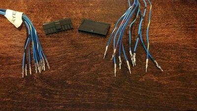
Here is a harness with terminal pins crimped onto the wires and ready to be installed into the connector housings. These particular connector housings are from the Molex Micro-fit family:
Tools of the Trade
Coming soon...
