Difference between revisions of "Wiring"
(→Specialty Connectors) |
(→IEC Fused Power Inlet with a Lighted Switch) |
||
| (15 intermediate revisions by 4 users not shown) | |||
| Line 60: | Line 60: | ||
[[Image:QuickDisconnects.jpg|300px]] | [[Image:QuickDisconnects.jpg|300px]] | ||
| + | |||
| + | The color of the vinyl sleeve indicates the gauge of wire it is designed for. | ||
| + | |||
| + | Yellow = 12-10 gauge | ||
| + | |||
| + | Blue = 16-14 gauge | ||
| + | |||
| + | Red = 22-18 gauge | ||
=====Bullet Connectors===== | =====Bullet Connectors===== | ||
| Line 80: | Line 88: | ||
[[Image:MolexMaleHousing.jpg|400px]] | [[Image:MolexMaleHousing.jpg|400px]] | ||
| + | |||
| + | |||
| + | Male and female housings with pins installed: | ||
| + | |||
| + | [[Image:MolexConnector.jpg|400px]] | ||
| Line 96: | Line 109: | ||
[[Image:InterfacesWired.jpg|400px]] | [[Image:InterfacesWired.jpg|400px]] | ||
| + | |||
| + | Here is a kick harness that uses a JST connector to connect to the game PCB: | ||
| + | |||
| + | [[Image:KickHarnessJST.jpg|400px]] | ||
=====Terminal Pins===== | =====Terminal Pins===== | ||
| + | Terminal pins are made specifically for use with their respective connector housings. Manufacturers and distributors usually make note of which pins are to be used with which housings. Most terminal pins require a special crimp, which can be made with a crimping tool designed to make that particular type of crimp. Once the pin has been crimped to the wire, it can be inserted and locked into the connector housing. | ||
| + | |||
| + | Here is an example of some terminal pins (and also a quick disconnect that uses the same type of crimp): | ||
| + | |||
| + | [[Image:TerminalPins.jpg|400px]] | ||
| + | |||
| + | |||
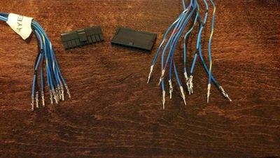
| + | Here is a harness with terminal pins crimped onto the wires and ready to be installed into the connector housings. These particular connector housings are from the Molex Micro-fit family: | ||
| + | |||
| + | [[Image:TerminalPinsInstalled.jpg|400px]] | ||
==Tools of the Trade== | ==Tools of the Trade== | ||
| Line 106: | Line 133: | ||
====Combination Tools==== | ====Combination Tools==== | ||
| + | |||
| + | ==IEC Fused Power Inlet with a Lighted Switch== | ||
| + | {{Template:DisclaimerElectricity}} | ||
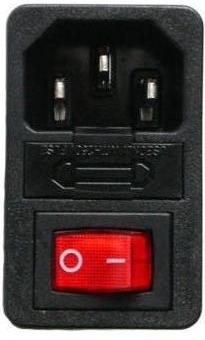
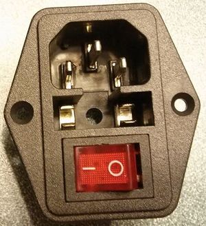
| + | [[image:IECPowerSwitch.jpg|right|thumb|IEC power inlet with fuse and lighted switch]] | ||
| + | One popular choice for neatly bringing power into a cab is a power inlet with an IEC320 C14 socket. | ||
| + | |||
| + | Some of them have built-in switches and/or fuse holders. | ||
| + | |||
| + | Fuses usually need to be ordered separately, remember to check the product description. | ||
| + | |||
| + | A number of vendors carry similar products with several different types of switches. | ||
| + | |||
| + | Two of the common illuminated switch configurations are shown below. | ||
| + | |||
| + | '''NOTE:''' Standard U.S. wiring colors are used below. | ||
| + | *Black = A.C. Hot | ||
| + | *White = A.C. Neutral | ||
| + | *Green = Ground | ||
| + | <br clear="all"> | ||
| + | ===3-Tab Switch=== | ||
| + | [[image:IEC3PinSwitchRear.jpg|240px]] | ||
| + | [[image:IEC3PinSwitchWiring.jpg|420px]] | ||
| + | <br clear="all"> | ||
| + | Hot (black) from the fuse output on 4 goes to 8, when the switch is closed it connects to 7 which goes to the cab. It also applies power to light the lamp. | ||
| + | |||
| + | Neutral (white) is daisy-chained from 1 to 6 to the rest of the cab. | ||
| + | |||
| + | The switch can be installed facing either way by the manufacturer -- 6, 7, 8 (shown) or 8, 7, 6. | ||
| + | |||
| + | The easiest way to tell which two terminals are actually 7 and 8 is to use your multimeter to check for continuity (<2 ohms) when the switch is in the "on" position, and an open when the switch is in the "off" position. Related thread with video [http://forum.arcadecontrols.com/index.php/topic,140543.msg1454938.html#msg1454938 here]. | ||
| + | |||
| + | As always, ensure that the power cord is NOT plugged in before using your multimeter in Continuity/Ohms mode or you'll fry your meter. | ||
| + | |||
| + | If you wire it with 7 and 8 reversed, the light will be lit all the time. | ||
| + | |||
| + | ===4-Tab Switch=== | ||
| + | [[image:IEC4PinSwitchRear.jpg|240px]] [[image:IEC4PinSwitchWiring.jpg|420px]] | ||
| + | <br clear="all"> | ||
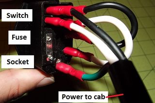
| + | The lamp is between D and B and when wired as shown, it only lights when the switch is closed -- swap the wires connected to A + B and the wires connected to C + D for the lamp to be always-on. | ||
| + | |||
| + | Outlet neutral (white) goes from 1 to A, when the switch is closed it connects to B which goes to the cab. | ||
| + | |||
| + | Hot from the fuse output on 4 goes to C, when the switch is closed it connects to D which goes to the cab. | ||
| + | |||
| + | [[image:IEC4PinSwitchWired.jpg|320px]] [[image:IECPowerStrip.jpg|274px]] | ||
| + | <br clear="all"> | ||
| + | |||
| + | ===Inspecting Power Wiring=== | ||
| + | Power wiring needs to have both solid mechanical '''and''' solid electrical connections. | ||
| + | |||
| + | Some Amazon reviews of IEC inlets mention problems such as melting and/or electrical fires. | ||
| + | |||
| + | These problems are caused by poor/high-resistance connections. | ||
| + | |||
| + | If only a few strands of the power cable are making solid contact with the terminal, the connection will still ohm out OK, but those strands will have to carry the entire electrical load over that narrow connection. | ||
| + | |||
| + | This can lead to a vicious cycle where the current flowing through that narrow connection generates heat which causes the wire to corrode which increases the connection resistance which generates more heat . . . | ||
| + | |||
| + | The same vicious cycle can be caused by contact corrosion as Badmouth discovered [http://forum.arcadecontrols.com/index.php/topic,137097.msg1414608.html#msg1414608 here] when he used an old power cable. | ||
| + | |||
| + | ====Inspecting Mechanical Power Connections==== | ||
| + | Test crimp connections by gently twisting the Quick Disconnect. (QD) | ||
| + | |||
| + | If the QD turns around the wire, recrimp or replace the QD. | ||
| + | |||
| + | If you test a poor crimp by pulling on the QD, it will pull off the wire and you will need to crimp a new QD in it's place. | ||
| + | |||
| + | ====Inspecting Electrical Power Connections==== | ||
| + | Verify the Hot, Neutral, and Ground connections using a multimeter to test the resistance from the (unplugged) power plug that plugs into the wall outlet to the power supply connection/power strip. (<2 ohms is good) | ||
| + | |||
| + | ====Using an Outlet Tester==== | ||
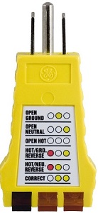
| + | [[image:Outlet Tester.jpg|right|thumb|Outlet tester]] | ||
| + | Once you've verified that you have solid mechanical and electrical connections, use an outlet tester to ensure that everything is wired correctly. (two yellow lights) | ||
| + | <br clear="all"> | ||
| + | |||
| + | ===Selecting a fuse=== | ||
| + | [[image:IECFuseHolder.jpg|right|thumb|IEC power inlet with fuse cover removed]] | ||
| + | When selecting a fuse for this enclosure, you will need one that has the right: | ||
| + | *Physical size | ||
| + | *Blow-time characteristic | ||
| + | *Voltage rating | ||
| + | *Amperage rating | ||
| + | |||
| + | Many enclosures use a 5mm x 20mm fuse -- be sure to check the product description because some use 5mm x 24mm or other size fuse. | ||
| + | |||
| + | Blow-time characteristic describes how long it takes for the fuse filament to melt when the amperage rating is exceeded. Using a slow-blow fuse will allow a short surge of current during power-on, but will melt if too much current flows through long enough. | ||
| + | |||
| + | The voltage rating indicates the maximum safe voltage to prevent arcing across a blown fuse. You can use a 250v fuse in a 125v circuit, but a 125v fuse should never be used in a 250v circuit. | ||
| + | |||
| + | The amperage rating indicates the maximum amount of current the fuse will handle without melting. One way to determine the required amperage is to take the wattage of the electronics you are protecting and divide by the voltage. i.e. a 650 watt computer power supply and a 100 watt LCD monitor on a 125v circuit will draw 6 amps. (750W/125v=6A) You'll want to pick a fuse that is rated higher than the expected current draw, such as a 7 or 8 amp fuse for this example. | ||
| + | |||
| + | '''REMEMBER''' you can pick fuses that are over-volt (higher voltage needed to arc) and/or under-amp (they will blow more often) compared to the proper rating -- getting it backward (under-volt or over-amp) is ''never'' acceptable. | ||
==See Also== | ==See Also== | ||
Latest revision as of 08:00, 31 October 2015
Contents
Wiring Techniques
This page will cover the different types of wiring practices to better help you decide on the best way to wire up your project.
Selecting Wire
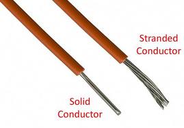
The size and type of wire used depends on the type of circuit it is being used in. Larger diameter wire is required for higher amperage circuits (A/C circuits of monitors and power supplies), whereas smaller diameter wire can be used in lower amperage circuits (control circuits). 22-24 gauge wire is a typical size used for wiring up control panels. 16-18 gauge wire is common for A/C power lines for things like power supplies and monitors. There are two basic types of wire: stranded and solid. Solid wire is more rigid and holds its shaped better than stranded wire. However, stranded wire is more flexible and easier to work with than solid wire.
Solid Wire
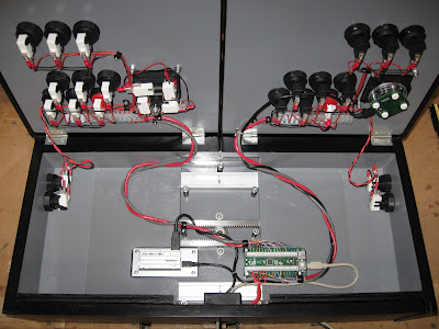
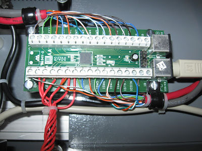
Typically, the only times you'll see solid wire being used in a project is when the builder uses CAT5 cable. Many people in this hobby come from computer backgrounds and use what they are familiar with, which is why some choose to use CAT5 cable for wiring their controls. They get multiple conductors in an easy to manage package. The wires inside the CAT5 cable are color coded which can make things a little easier when wiring up your controls. Here is a clean example, done by user TopJimmyCooks, of a CP wired using mainly CAT5 cable:
And a close up of his CAT5 wired to his interface of choice for this project, an I-PAC:
Stranded Wire
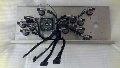
Wiring harnesses in original cabinets utilized stranded wire. Often called "hookup wire", it is readily available from auto parts stores and home improvement stores. Many builders choose to use stranded wire in their projects. Stranded wire is easier to crimp and solder than solid wire. Here is an example of an installed CP harness made with stranded wire:
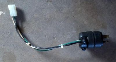
Here is a power plug wired to a Molex connector, using 16 gauge stranded wire, to connect to a stock arcade machine power supply harness:
Connecting Wires
There is a vast variety of different types of connectors to choose from for wiring your project. While they all will work, some are better/safer to use than others. Sure, you can simply twist two wire ends together and tape the connection, but that is not very safe. The easiest safe way to connect wires is by using some type of connector. You can also solder wires together to create a strong, dependable connection.
Common Connectors
The most common way of connecting one wire to another is by using one of the following types of connectors. These connectors can be found at any hardware, auto parts, or home improvement store. They can come in either insulated or non-insulated varieties, but it is always wise to insulated connectors to reduce the likelyhood of unintentional short circuits.
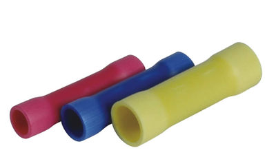
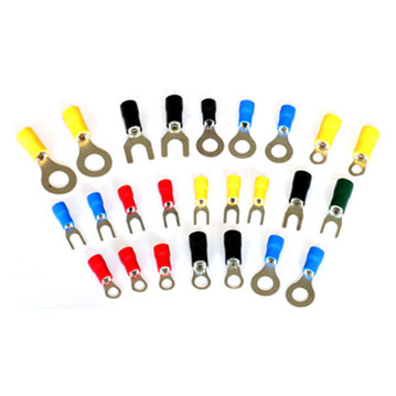
You will notice that many of these connectors come in red, blue, and yellow. This color code is used to indicate a range of wire gauges that the connectors should be used with. Red is for 18-22 gauge wire, blue is for 14-16 gauge wire, and yellow is for 10-12 gauge wire.
Wire Nuts
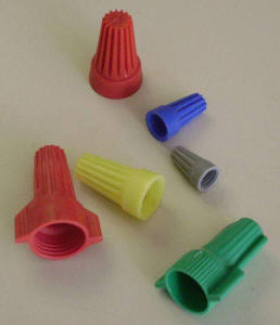
Wire nuts are most commonly used in electrical systems of buildings. You will see them used to connect the building's wiring inside electrical boxes for lights, switches, and outlets. They mostly used with solid wire, but can be used with stranded as well. They make for a quick, reversable wire connection. No crimping tool is needed, only wire strippers. Typically not recommended for use in this hobby.
Scotch Locks
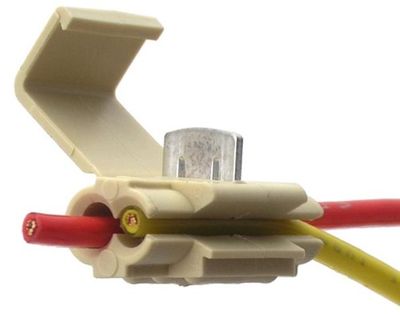
Scotch locks are the lazy man's connector of choice. No tools are required for the scotch lock. The scotch lock makes the connection between the wires by piercing the wires' insulation and wedging the conductors into the internal grooves of the scotch lock. Not recommended, they're ugly, and there's a better way.
Butt Splices
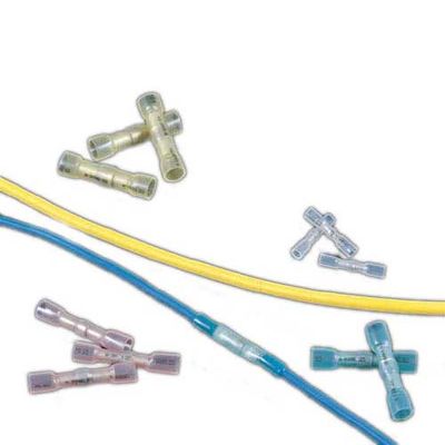
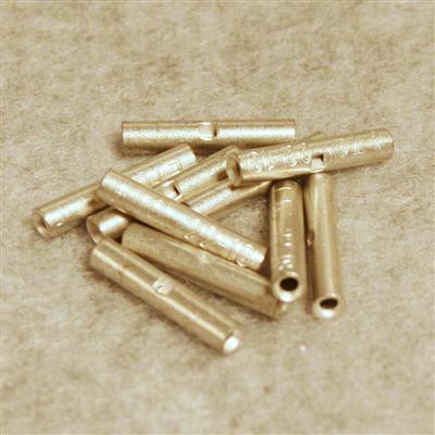
Butt splices connect one wire end to another wire end. The connection cannot be disconnected without cutting the butt splice out. They are handy for adding more length to a wire you find is too short. They are available in non-insulated, insulated, and heat shrink types. It is recommended that you used a heat shrink tube over a non-insulated butt splice.
Heat Shrink Butt Splices:
Insulated Butt Splices:
Non-Insulated Butt Splices:
Quick Disconnects
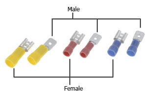
As their name implies, quick disconnects are designed to make a wire connection that can be disconnected and reconnected at will. Quick disconnects are used on nearly all arcade control panels. You will find them used on button and joystick microswitches. They commonly come in three different widths: .110", .187", and .250". The most common width used on arcade parts is .187". Many microswitches have a shouldered terminal which allows the use of either .187" or .250" quick disconnects. They are available in a male for female configuration. Since the microswitch terminals are male, female quick disconnects are used to connect wires to those terminals. There is a wide variety of quick disconnects as well.
The color of the vinyl sleeve indicates the gauge of wire it is designed for.
Yellow = 12-10 gauge
Blue = 16-14 gauge
Red = 22-18 gauge
Bullet Connectors
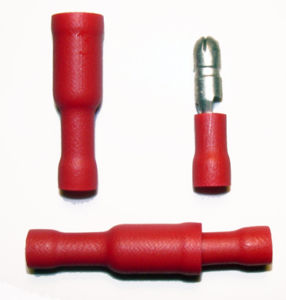
Bullet connectors are similar to quick disconnects in the fact that they can be disconnected and reconnected at will. However, this type of connection isn't typically found on electrical parts such as switches. These can be used in a similar manner as butt splices if you want to have a particular connection be able to be disconnected without cutting wires.
Ring/Spade Terminals
Ring and spade terminals are typically used to connect a wire to a screw terminal, such as found on arcade switching power supplies and many earth ground connections. To remove a ring terminal, the screw has to be completely backed out. However, to remove a spade terminal, the screw only needs to be loosened to allow the spade terminal to be slipped out.
Specialty Connectors
Along with the common types of connectors listed above, you will also encounter other types of "stock", "specialty", or "professional" connectors. The most common of these you'll find in original arcade machines are Molex type connectors. You will also find connectors made by other manufacturers, such as JST. These connectors are typically a hard plastic housing that contains multiple wires. A terminal pin is crimped onto the end of each wire, and the pins then lock into the housing. There are male and female pins, as well as male and female housings. Normally, male pins will install in female housings which mate with female pins installed into male housings.
Vendors often offer products that incorporate screw type terminals for easy installation. However, some products are also available that utilize the use of some type of specialty connector, usually one that connects to a straight pin header on a PCB. Vendors will offer premade harnesses for use with these products, but that doesn't mean you can't make your own. With the right tools, you can make your own harnesses with these professional looking connectors. The tools will be covered in a following section.
Connector Housings
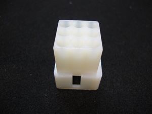
Here is an example of the Molex connector type often found in arcade machines (this is a male housing):
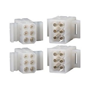
Male and female housings with pins installed:
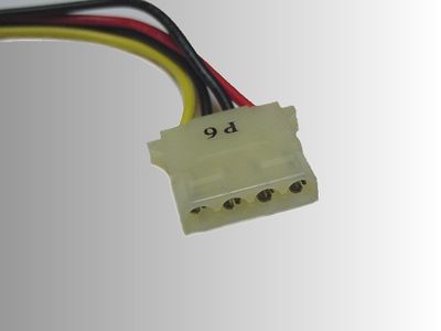
Here is another type of Molex connector often found in this hobby, a connector of a computer's power supply harness. This is a male housing and if you look closely you can see that the terminal pins are female:
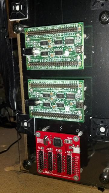
Here are some examples of interface boards that utilize straight pin headers. Two of Ultimarc's PACLED64s on the top and Paradise Arcade Shop's Lono2:
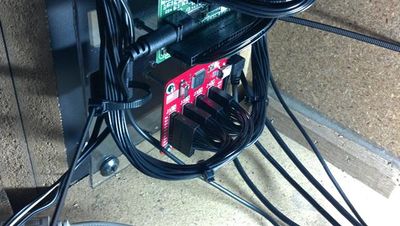
Here those same interface boards are wired up with homemade harnesses using connectors manufactured by Molex. The headers used on these interfaces are a common size and pitch (the same as what is used for USB headers on computer motherboards) and other manufaturers also make connectors to mate with these types of headers:
Here is a kick harness that uses a JST connector to connect to the game PCB:
Terminal Pins
Terminal pins are made specifically for use with their respective connector housings. Manufacturers and distributors usually make note of which pins are to be used with which housings. Most terminal pins require a special crimp, which can be made with a crimping tool designed to make that particular type of crimp. Once the pin has been crimped to the wire, it can be inserted and locked into the connector housing.
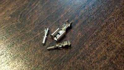
Here is an example of some terminal pins (and also a quick disconnect that uses the same type of crimp):
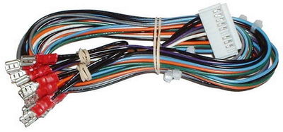
Here is a harness with terminal pins crimped onto the wires and ready to be installed into the connector housings. These particular connector housings are from the Molex Micro-fit family:
Tools of the Trade
Coming soon...
Cutters
Strippers
Crimpers
Combination Tools
IEC Fused Power Inlet with a Lighted Switch
| ---DISCLAIMER--- |
| This Wikipage explains how to modify or connect electric equipment. Build Your Own Arcade Controls Wiki recommends reading the manuals of the tools and equipment you are using.
|
One popular choice for neatly bringing power into a cab is a power inlet with an IEC320 C14 socket.
Some of them have built-in switches and/or fuse holders.
Fuses usually need to be ordered separately, remember to check the product description.
A number of vendors carry similar products with several different types of switches.
Two of the common illuminated switch configurations are shown below.
NOTE: Standard U.S. wiring colors are used below.
- Black = A.C. Hot
- White = A.C. Neutral
- Green = Ground
3-Tab Switch
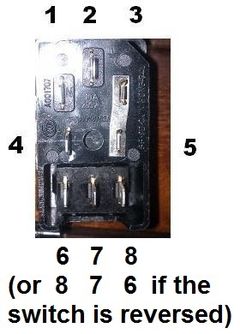
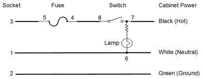
Hot (black) from the fuse output on 4 goes to 8, when the switch is closed it connects to 7 which goes to the cab. It also applies power to light the lamp.
Neutral (white) is daisy-chained from 1 to 6 to the rest of the cab.
The switch can be installed facing either way by the manufacturer -- 6, 7, 8 (shown) or 8, 7, 6.
The easiest way to tell which two terminals are actually 7 and 8 is to use your multimeter to check for continuity (<2 ohms) when the switch is in the "on" position, and an open when the switch is in the "off" position. Related thread with video here.
As always, ensure that the power cord is NOT plugged in before using your multimeter in Continuity/Ohms mode or you'll fry your meter.
If you wire it with 7 and 8 reversed, the light will be lit all the time.
4-Tab Switch
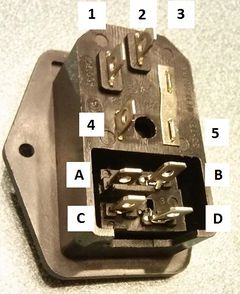
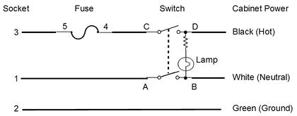
The lamp is between D and B and when wired as shown, it only lights when the switch is closed -- swap the wires connected to A + B and the wires connected to C + D for the lamp to be always-on.
Outlet neutral (white) goes from 1 to A, when the switch is closed it connects to B which goes to the cab.
Hot from the fuse output on 4 goes to C, when the switch is closed it connects to D which goes to the cab.
Inspecting Power Wiring
Power wiring needs to have both solid mechanical and solid electrical connections.
Some Amazon reviews of IEC inlets mention problems such as melting and/or electrical fires.
These problems are caused by poor/high-resistance connections.
If only a few strands of the power cable are making solid contact with the terminal, the connection will still ohm out OK, but those strands will have to carry the entire electrical load over that narrow connection.
This can lead to a vicious cycle where the current flowing through that narrow connection generates heat which causes the wire to corrode which increases the connection resistance which generates more heat . . .
The same vicious cycle can be caused by contact corrosion as Badmouth discovered here when he used an old power cable.
Inspecting Mechanical Power Connections
Test crimp connections by gently twisting the Quick Disconnect. (QD)
If the QD turns around the wire, recrimp or replace the QD.
If you test a poor crimp by pulling on the QD, it will pull off the wire and you will need to crimp a new QD in it's place.
Inspecting Electrical Power Connections
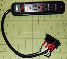
Verify the Hot, Neutral, and Ground connections using a multimeter to test the resistance from the (unplugged) power plug that plugs into the wall outlet to the power supply connection/power strip. (<2 ohms is good)
Using an Outlet Tester
Once you've verified that you have solid mechanical and electrical connections, use an outlet tester to ensure that everything is wired correctly. (two yellow lights)
Selecting a fuse
When selecting a fuse for this enclosure, you will need one that has the right:
- Physical size
- Blow-time characteristic
- Voltage rating
- Amperage rating
Many enclosures use a 5mm x 20mm fuse -- be sure to check the product description because some use 5mm x 24mm or other size fuse.
Blow-time characteristic describes how long it takes for the fuse filament to melt when the amperage rating is exceeded. Using a slow-blow fuse will allow a short surge of current during power-on, but will melt if too much current flows through long enough.
The voltage rating indicates the maximum safe voltage to prevent arcing across a blown fuse. You can use a 250v fuse in a 125v circuit, but a 125v fuse should never be used in a 250v circuit.
The amperage rating indicates the maximum amount of current the fuse will handle without melting. One way to determine the required amperage is to take the wattage of the electronics you are protecting and divide by the voltage. i.e. a 650 watt computer power supply and a 100 watt LCD monitor on a 125v circuit will draw 6 amps. (750W/125v=6A) You'll want to pick a fuse that is rated higher than the expected current draw, such as a 7 or 8 amp fuse for this example.
REMEMBER you can pick fuses that are over-volt (higher voltage needed to arc) and/or under-amp (they will blow more often) compared to the proper rating -- getting it backward (under-volt or over-amp) is never acceptable.
