Difference between revisions of "Yoke Rebuild"
| (One intermediate revision by the same user not shown) | |||
| Line 1: | Line 1: | ||
This page is a documentation of a complete teardown, refurbish (paint & lube), and rebuild of an Atari Star Wars type yoke control. | This page is a documentation of a complete teardown, refurbish (paint & lube), and rebuild of an Atari Star Wars type yoke control. | ||
| − | Replacement parts now available at | + | Replacement parts now available at http://arcadefixit.com |
The Star Wars Operator's Manual is available at | The Star Wars Operator's Manual is available at | ||
| Line 26: | Line 26: | ||
NOTE: Wires, potentiometers (pots), and microswitches may differ from original. This guide also assumes you have already removed the outer cover. | NOTE: Wires, potentiometers (pots), and microswitches may differ from original. This guide also assumes you have already removed the outer cover. | ||
| + | |||
| + | There are 4 main wire 3-wire bundles going to the left handle, right handle, X-axis pot and Y-axis pot. | ||
| + | |||
| + | Take pictures of how the wires are connected on your yoke and label the bundles for easier re-assembly later. | ||
| + | |||
| + | [[Image:yoke_wire_label.jpg]] | ||
'''SAVE EVERYTHING YOU REMOVE FROM THE YOKE (EVEN IF REPLACING) UNTIL IT IS REBUILT''' | '''SAVE EVERYTHING YOU REMOVE FROM THE YOKE (EVEN IF REPLACING) UNTIL IT IS REBUILT''' | ||
Latest revision as of 01:54, 19 October 2015
This page is a documentation of a complete teardown, refurbish (paint & lube), and rebuild of an Atari Star Wars type yoke control.
Replacement parts now available at http://arcadefixit.com
The Star Wars Operator's Manual is available at http://www.arcade-museum.com/manuals-videogames/S/StarWars.pdf (see pages 51-53 for the yoke exploded view and parts list)
Also, a source for METAL replacement gears is W.M. BERG: http://www.wmberg.com/
NOTE: I have not tested these gears for compatibility and some (specifically the 60 tooth gears) would at least require drilling out the bore to accommodate the diameter of the steering/handle shafts, but the following are my best estimates as to replacement gear part numbers:
14 tooth Y-axis pot gear: P24A66-14 (in ANODIZED ALUMINUM) or P24PH28-14 (in STAINLESS STEEL)
28 tooth X-axis pot gear: P24PH28-28 (in STAINLESS STEEL)
60 tooth X/Y-axis shaft gear: P24B34X-60 (BRASS or BRONZE - it's unclear) or P24A68-60, P24A67-60, P24A66-60 (in ANODIZED ALUMINUM) or P24S35-60, P24S34X-60 (in STAINLESS STEEL)
... but do your homework and make sure these will work before ordering.
The Guide
NOTE: Wires, potentiometers (pots), and microswitches may differ from original. This guide also assumes you have already removed the outer cover.
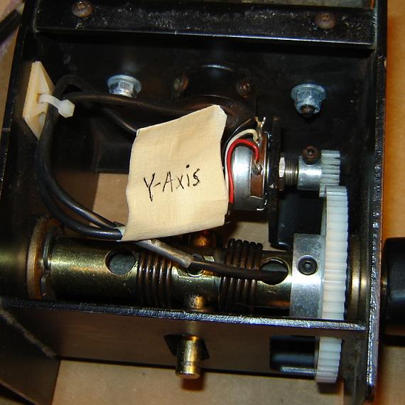
There are 4 main wire 3-wire bundles going to the left handle, right handle, X-axis pot and Y-axis pot.
Take pictures of how the wires are connected on your yoke and label the bundles for easier re-assembly later.
SAVE EVERYTHING YOU REMOVE FROM THE YOKE (EVEN IF REPLACING) UNTIL IT IS REBUILT
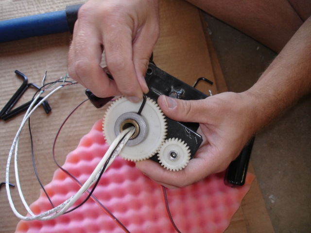
Step 1: Loosen X-axis pot retainer nut with 1/2" wrench. Remove shoulder bolt from X-axis pot 28-tooth spur gear hub using allen wrench. Remove spur gear from pot.
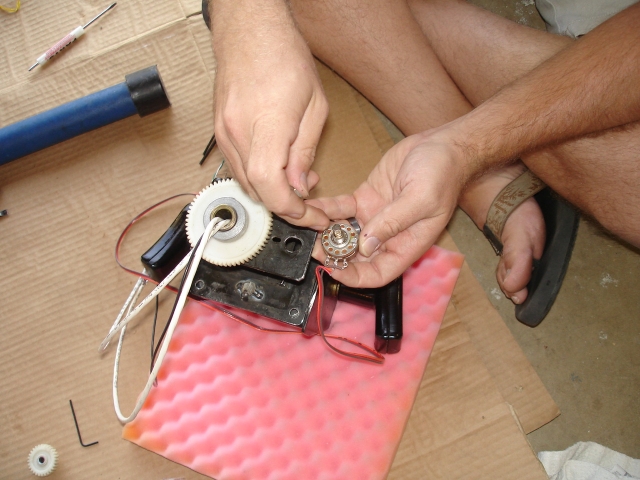
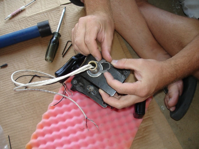
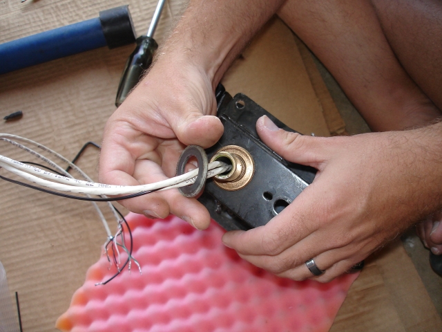
Step 2: Remove X-axis pot retainer nut and star washer. Remove Pot.
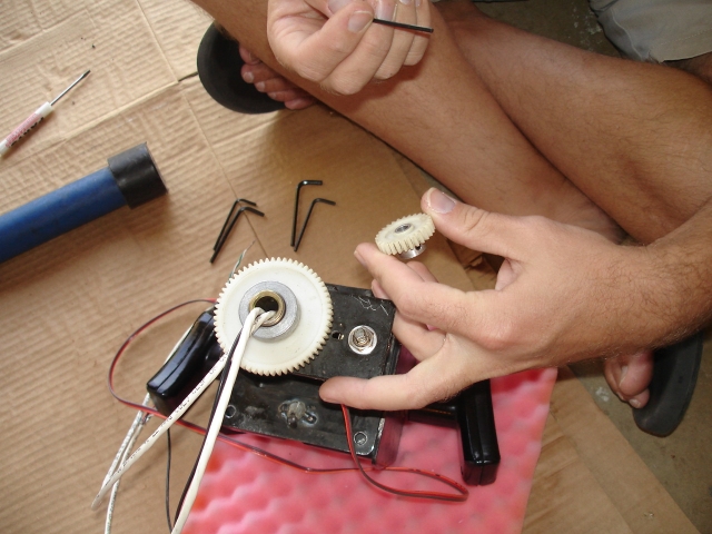
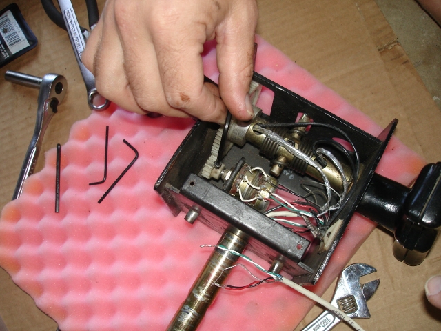
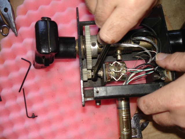
Step 3: Remove shoulder bolt from X-axis shaft 60-tooth spur gear hub using allen wrench. Remove spur gear from shaft.
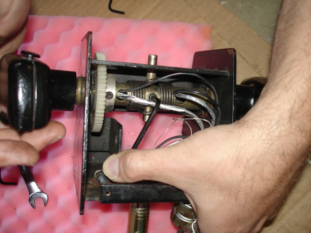
Step 4: Remove C-clip using flathead screwdriver.
Insert a large common screwdriver between the belly of the C-clip and the shaft -- twist the screwdriver to push the clip away from the shaft and be sure the "downrange" area is prepped in case the clip launches.
Step 5: Remove shaft washer.
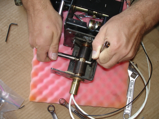
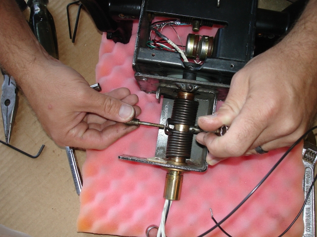
Step 6: Loosen anchor pin using 5/16" wrench or socket. Hold anchor nut using another 5/16" wrench
Step 7: Remove anchor pin and nut. Rotate steering assembly frame while doing so to relieve spring tension on pin and nut.
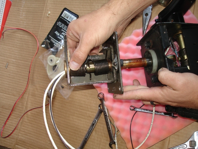
Step 8: Slide torsion springs and steering assembly frame off the steering shaft.
Step 9: Remove bump stops (if they exist) from metal pins on steering assembly frame and handle assembly frame (4 total).
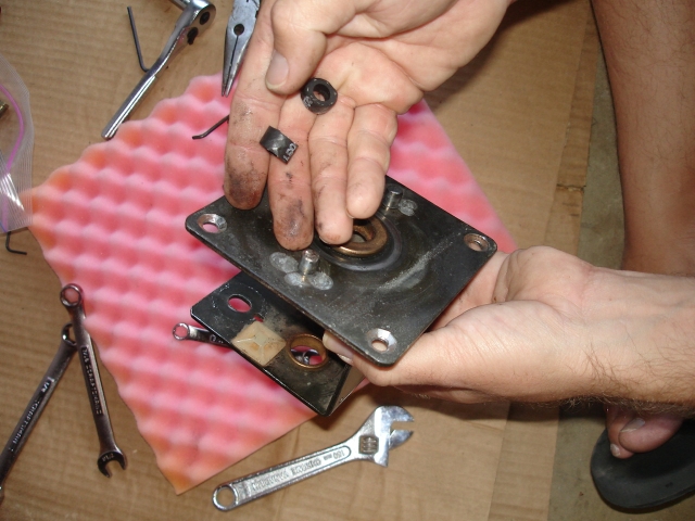
Step 10: Remove white plastic bushing from steering shaft.
Step 11: Remove shoulder bolt from handle assembly frame steering shaft hub using allen wrench. 3 total (one on underside).
Step 12: Remove steering shaft from handle assembly frame.
Step 13: Loosen Y-axis pot retainer nut with 1/2" wrench. Loosen set screw from Y-axis pot 14-tooth spur gear hub using allen wrench.
Step 14: Remove spur gear from pot. A 3/8" wrench is handy as a gear puller.
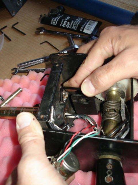
Step 15: Remove bolt from Y-axis shaft limiter pin using allen wrench. Rotate handles while doing so to relieve spring tension on pin.
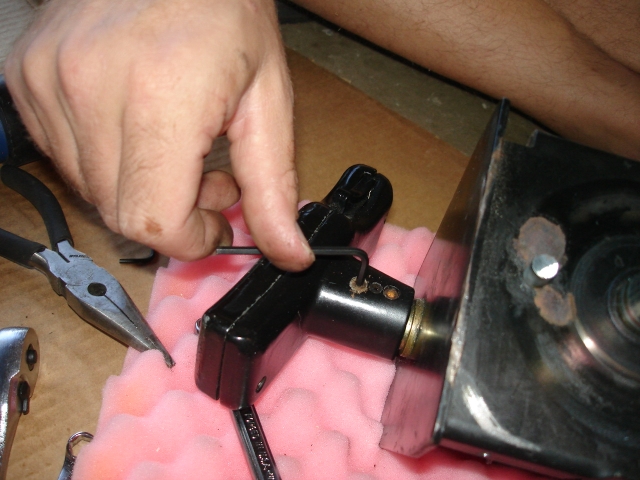
Step 16: Remove outer and inner shoulder bolt from handle hub using allen wrench.
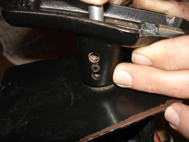
Step 17: Wonder why the handle won't come off. Wonder what that other thing is between the outer and inner shoulder bolt holes. Realize it is a pressed-in spring pin. Ponder how to get it out.
NOTE: The method for removing the spring pin from the shaft as outlined in steps 18-20 is a technique but not doctrine. Using a mallet and a pair of pliers, small screwdriver, or awl one can drive the spring pin through the handle into the shaft very easily. Please see the following link for a brief video explanation: http://www.youtube.com/watch?v=kRyguLuRLN8
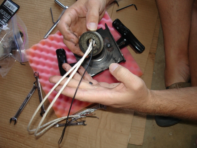
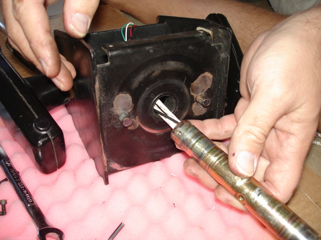
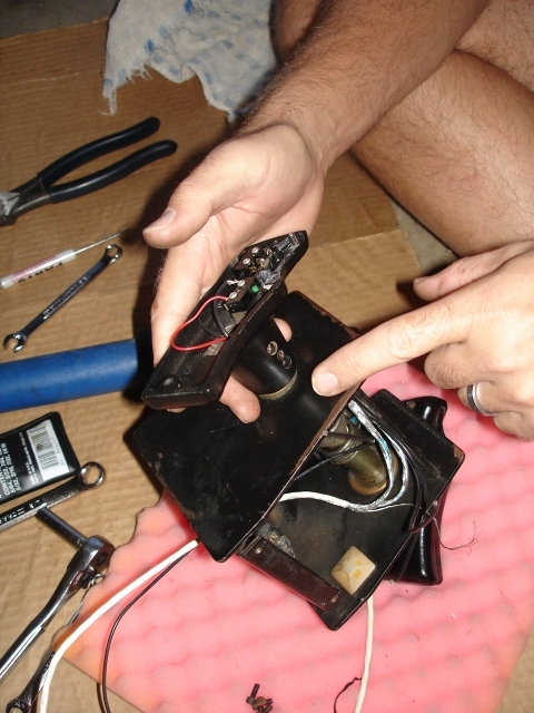
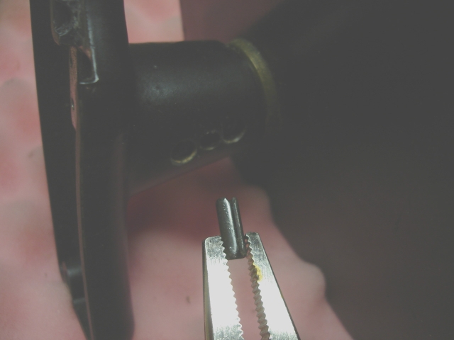
Step 18: Cut wires free from microswitches. Pull wires back through handle shaft. Remove microswitch bolts using screwdriver and remove microswitches. Use screwdriver inside handle shaft to push spring pin outwards.
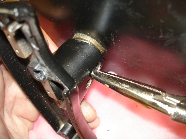
Step 19: Grip spring pin with vise grips and pull. Repeat until spring pin actually comes out. At some point, you may be able to rotate it a bit while pulling.
Step 20: Marvel at the fact you have triumphed over an inanimate 4 cent piece of steel. Repeat steps 16-20 for other handle (if you want/need to - the other handle could stay on the handle shaft).
TIP: I was finally able to get the second spring pin out by gripping it in the edge of a vise with a good sharp edge on the jaw and put sandpaper in between the vise jaw and the pin for extra grip.
Remove shoulder bolt from Y-axis shaft 60-tooth spur gear hub using allen wrench. NOTE: Be sure to verify that the right-hand side of the shaft has the threaded hole for the gear screw when you start to reassemble the yoke.
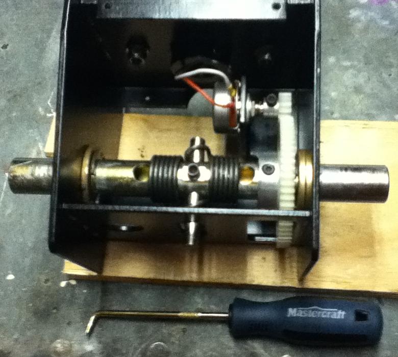
Remove C-clips using hook pick or other tool like the one shown below, but be extremely cautious if prying with a screwdriver as it would be too easy to damage the plastic (but expensive to replace) gear.
Slide handle shaft out of handle assembly frame, torsion springs, and gear.
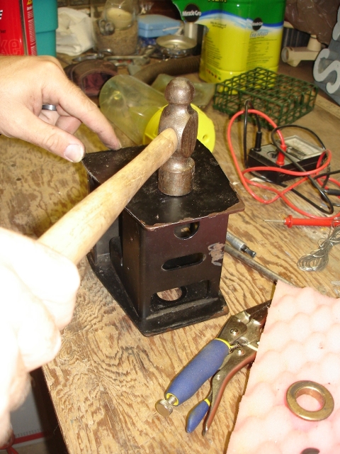
Step 21: Gently tap handle shaft bearing towards interior of handle assembly frame using hammer.
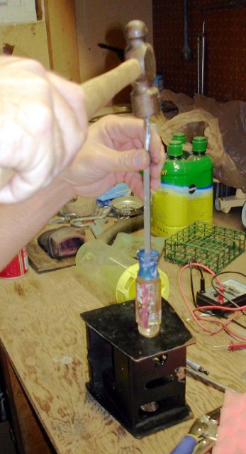
Step 22: The ball end on my screwdriver worked well to free the bearing from the handle assembly frame.
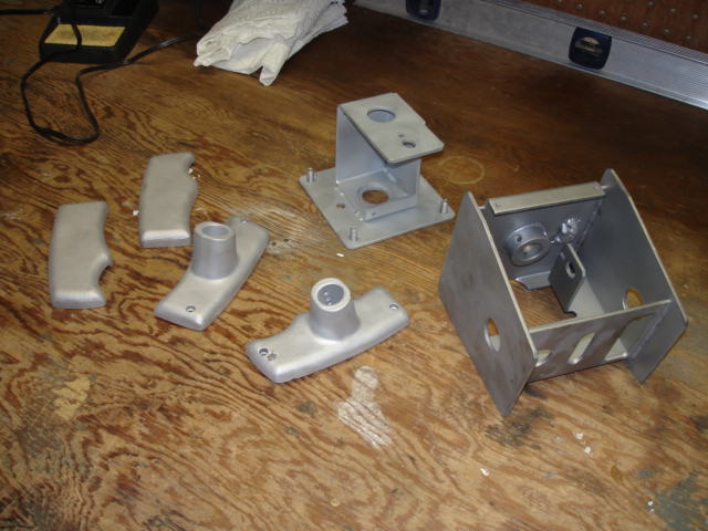
Step 23: Strip paint off the handles, handle assembly frame, and steering assembly frame. Bead blasting worked great for me. One of my handles had a nick out of it - I'm guessing this was a casting flaw. I patched it with JB Weld and sanded it down.
(WARNING: NAKED YOKE!)
